
The crankcase halves, cylinder heads etc. have all come back from the aqua-blasters and they are now lovely and clean, so I can commence rebuilding the engine for my 1971 Karmann Ghia Convertible.

Next up is a spacer, that simply slides on and then the brass distributor drive gear. This also needs heating up before sliding on. Now with all those in place it was time to fit the retaining circlip. You need some really strong circlip pliers to open this heavyweight clip and once in place it's a good idea to tap the circlip down into the groove to ensure that it is seated properly.
Now the small main bearing can be slipped on, again ensuring that the dowel pin hole is towards the flywheel end and finally the oil thrower and the final woodruff key for the fan belt pulley.
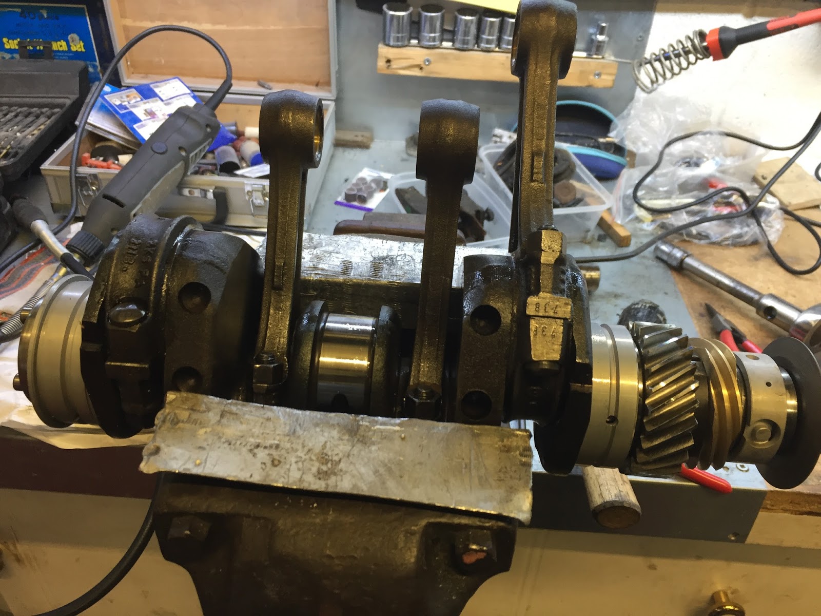
 I must admit at this point I was feeling pretty confident and that usually comes before a fall! Time to offer the crankshaft into the crankcase. So with the split centre main bearing in place and the flywheel main bearing slid over the end of the crankshaft, I carefully lowered the crankshaft into place. Now came the delicate task of rotating the three, non-split, bearings until they locate with the dowel pins in the crankcase.The flywheel bearing rotated and clicked onto the dowel beautifully, as did the small back bearing, but the one next to the camshaft gear was more difficult as the "click" was really difficult to feel and it was a long time before I was happy that it was it place. Now I could fit the camshaft bearings and the four cam followers that sit under the camshaft. Then the camshaft could be fitted. There are two teeth on the crankshaft gear that are marked with a centre-pop mark and one tooth on the camshaft that is marked with a circle. To get the valve timing correct, the circle must sit between the two centre-popped teeth. That done, I was almost ready to put the top half of the crankcase on. All I needed was the core plug that fits at the flywheel end of the camshaft. But no matter where I looked, I couldn't find it. I searched everywhere I and finally decided that I must have left it stuck in one half of the crankcase when I sent it for blasting and they've come back without it. Apart from the delay, I didn't see a problem and ordered a new one from VW Heritage at 70p. When it arrived it was exactly as I expected, a small metal cap, with a protruding ridge around it, just as I remembered from the 1960's.
You will remember that I said "confidence usually comes before a fall", well from here onwards everything starts to go wrong.
I took the new core plug into the workshop and offered it up to the crankcase. I then realised that my crankcase has no corresponding groove for the core plug to fit into. Internet investigation revealed that Brazilian engines were fitted with a "rubber" core plug. I rang VW Heritage and they didn't have one. So I tried e-mailing dozens of VW based businesses world wide and eventually someone replied who had one and a week later it arrived. Cost £8.90.
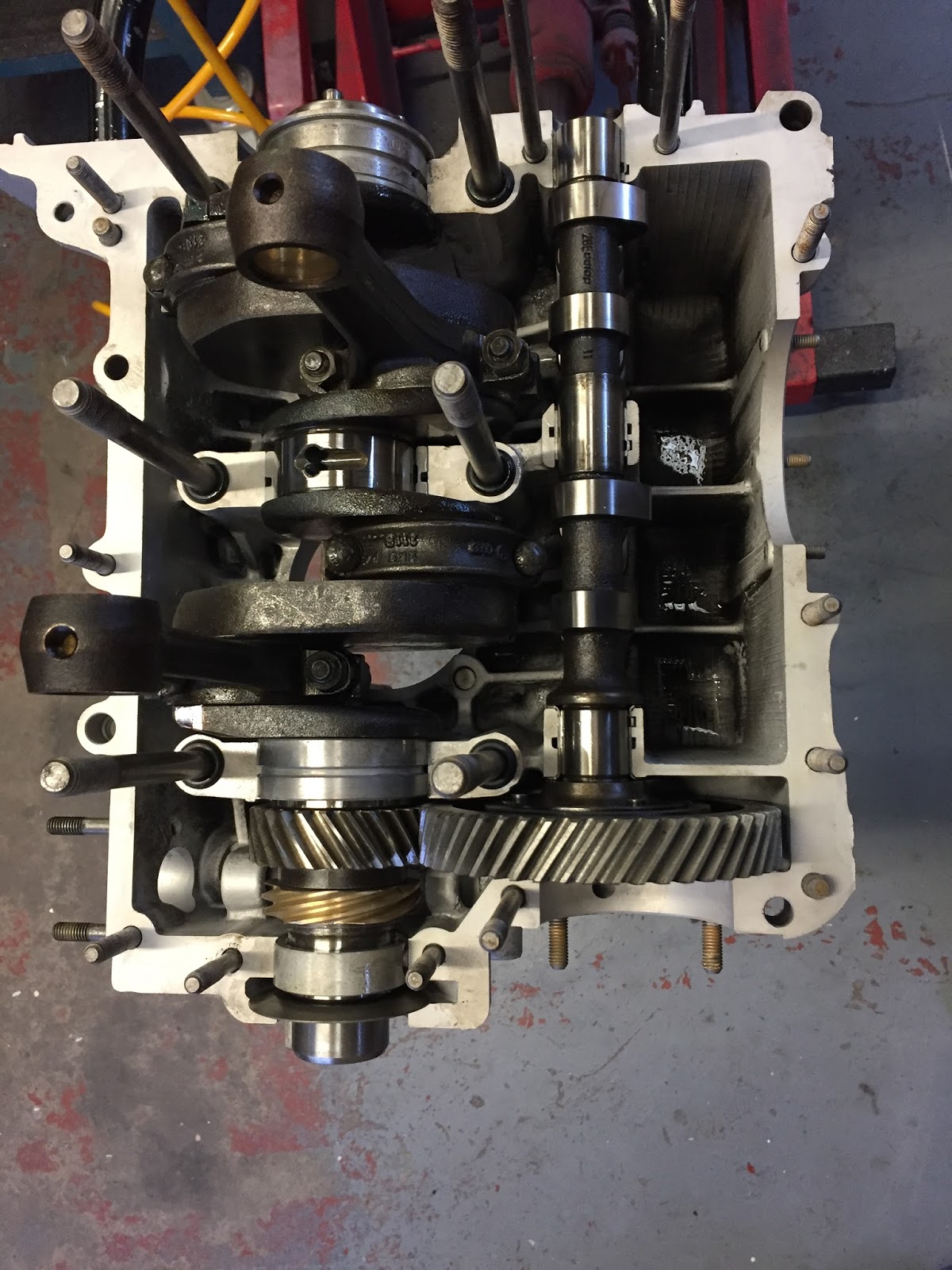
 So at last I could put the two crankcase halves together. But first I had to figure out how to hold the other four cam followers, in the top half of the crankcase, in place whilst I held it upside down. The answer came from a wire coat hanger, wound around a broom handle to create two spring clips. I carefully put a thin layer of blue gasket sealant around the edge of the case and lowered it into place. Then with a torque wrench I tightened the six 12mm nuts down and then all of the 8mm fixings around the edge of the case.
 One final check, to ensure that the crankshaft is still free to turn and it wasn't!!! The crankshaft was locked solid and the only thing I could do was strip the whole thing down again. And it got worse.
 Inspection of the main bearing next to the camshaft gear showed had not been seated on the dowel, as I thought, and the tightening down process had indented the bearing and pressed it right through onto the inner surface, rendering the bearing useless. Furthermore I found that you could not buy just one bearing and had to buy a full set. What's more I had to heat up and strip all of the gears off the end of the crankshaft again to remove the bearing and doing so damaged the brass distributor gear with the puller.
I was not a happy bunny and the replacement parts cost me another £65. Careful examination of the crankcase revealed that the dowel for this bearing sat lower than all of the other dowels, making it impossible to feel when locating the bearing.
When the new ones arrived I decided to take a different approach. This time I mounted all of the bearings in the crankcase before fitting them to the crankshaft. With the bearings in place and located on their dowels, I took a felt tip pen and marked both sides of the bearing where it lined up with the crankcase. Now when the crankshaft is lowered into place, if I can see all of the black lines, then the dowel holes are directly downwards. I then had to go through the whole procedure again, heating up gears, rebuilding the crankshaft, refitting the camshaft etc. But this time it bolted down and the crankshaft still turned freely. Lesson learnt.

Now with the crankcase together I could look at continuing the rebuild and I felt that the oil pump would be a good place to start. So I found the appropriate gaskets and put the one, that fits between the oil pump and the crankcase, on top of the engine so that I wouldn't forget it whilst I prepared the pump itself. The pump was in excellent condition but filthy and not fit to put on my nice clean crankcase. So into the parts washer bath along with the steel plate cover and then a good scrub and then a trip into the polishing shed to clean up the aluminium edge on the pump. That done I put a nice thin coat of blue sealant onto the crankcase and knocked the pump in, onto its four studs with a soft faced hammer. I was just thinking how nice it looked, when I noticed the gasket still sitting on the top of the engine. "Oh bother" I said (or something like that).
Knocking the oil pump in is one thing, but getting it out again is quite another. I consulted the manual and it was very specific. "Do not try to lever the oil pump out of the crank case, this will irrecoverably damage the mating surfaces". Apparently there are only two ways of removing the pump.
1. Split the crankcase again.
2. Use the special VW oil pump extractor.
After all the trouble I had, there was no way, I was going to split the crankcase again. So that left the special tool, that I don't have!
 I decided to take a look at the pump and see if I could figure out how this special tool could work. The only thing that I could see that a tool could get hold of was the two oil ways, left and right, which are basically two holes in the sides of the pump body about 8mm in diameter. I decided that a metal rod between these two holes that I could pull on was the answer. So I found an 8mm bolt and cut the head off. I then put the bolt in the lathe and turned it down until it fit inside the two holes. This also involved filing a curve out of the centre of the bolt to clear the shaft that supports the idler gear in the pump. Now how to pull on the rod? I found a piece of 10mm threaded rod and welded it to the centre of the turned down bolt. I could now slide the bolt into one oil way and then slide the whole thing across to locate in the hole on the other side. Now all I needed was a "U" shaped piece of metal to fit either side of the pump and I could pull it out. At last a little luck, instead of having to make one, I found a Lambretta clutch compressor that suited the job perfectly. So with the centre bolt removed from the compressor and my threaded rod inserted, all I had to do was tighten the nut and the oil pump pulled out perfectly.
Now I could fit the offending gasket, refit the pump, add the outer gasket and bolt down the metal cover plate. Not the best day I have ever had but at least it ended well. Next will be the pistons, cylinders and heads. Fingers crossed I don't make any more silly mistakes.

You can contact me on hopcroftscoot@gmail.com
Copyright 04.10.17 all rights reserved.
My Other Blogs:
1961 BSA A10 Super Rocket Motorcycle:
http://60sclassicmotorbikes.blogspot.co.uk/2012/07/before.html
1961 Ariel Arrow Super Sport Motorcycle :
http://60sclassicmotorbikes.blogspot.co.uk/2014/01/1961-aerial-golden-arrow-restoration.html
Miniature Land Rover Defender:
http://miniaturelandrover.blogspot.co.uk/2016/02/1-miniature-land-rover-defender-idea.html?view=timeslide
Motorcycle Trailers / Caravans:
http://motorcycletrailersandcaravans.blogspot.co.uk/2018/01/1-motorcycle-trailers-problem.html
No comments:
Post a Comment