Saturday, 22 January 2022

21. Karmann Ghia Restorations - The Doors


Well it's been a very long time since my last blog and progress has been very slow, mostly due to Covid lockdown. But I am finally making progress. As I mentioned on my last blog, my next job was to weld new pieces of metal onto the kickboards under the rear seat. This was done and painted and looked OK. 

I was then looking at my new wheels and the wheel well at the front of the car and decided to try one of the new wheels into the hole. Well surprise surprise, it didn't fit! The new wheel and tyre being bigger would not go down into the well and the horn support bracket and jack clamp all got it the way. Well there was nothing for it but to remove both brackets and then panel beat the inner wings on both sides to widen the wheel well. 


That done I could then try the new wheel in the well and find a new position for the jack clamp and weld it back into place. I then had to design and make a new horn bracket and try that in place with the horn attached to ensure that it would not foul the spare wheel. Designing the new horn bracket was more complicated than I had expected as I had to ensure that I could adjust it's position, with the horn on it, with the spare wheel in place. This involved drilling a hole in the bodywork and bolting the new bracket in place, then turning the bracket until everything cleared the wheel. Once in the right place, the bracket could be welded in place. The bolt could then be removed and the hole welded up again. But there it is, done.


Now the job I have not been looking forward to. The doors. Inspection of the doors showed rot at the bottom of each door, but this only required plating and welding. The main problem was down the slot on the top where the window passes through. Just inside this slot are two plates, one on each side. These plates carry 7 rubber buffers, that fit either side of the window to stop it rattling. The holes that carry these buffers had rotted away. I had no choice but to cut open the top of the doors and make new plates. Here you can see the door cut open and one of the new plates held in place ready for welding. I was lucky when making the plates that my small press was just wide enough to do the small bend along the top edge. The holes that you can see in the new plate for the buffers were drilled right through with the door. The other holes, only in the new plate, are for welding through to hold the plate in place.

The top of the door then had to be carefully welded back on again and refinished to a smooth condition. The whole process then had to be repeated for the other door. 


The whole process took days  but in the end the doors were fit to spray and use.


Finally the doors could be fitted to the body to see if they still fit and amazingly, they do!! I then had to look at the chrome trim fixing holes down the side of the body. Now the ones in the doors were still there but most of the ones on the replacement body panels were missing. So, to get them in the right places, I used a laser to project a straight line onto the side of the body, passing through as many holes as possible and then marked and drilled the new ones in place. It's interesting to note that the indentations on the replacement panels, for the holes, were all in the wrong places.


I could now refit the rear boot lid and that just leaves the bonnet (Hood) to be fitted and the body can go off for paint.

So, I have actually booked the body in for paint in two weeks time. 

Now having booked that, it has now occurred to me that, as I had so much trouble getting the spare wheel to fit, will the new wheels and tyres fit under the wheel arches?? So my next job is to fit the body onto the chassis and try the wheels in place. FINGERS CROSSED!!


Saturday, 5 June 2021

20. Karmann Ghia Restoration - Do Things Fit?


I've now reached the stage where I need to check if things fit, on my Karmann Ghia restoration, before the body goes off for painting. So the first thing to take a look at is the bumpers. Now I had already bought replacement, stainless steel, bumpers and whilst waiting for my friend to do more welding, I had successfully assembled them and been saving them for this moment. 

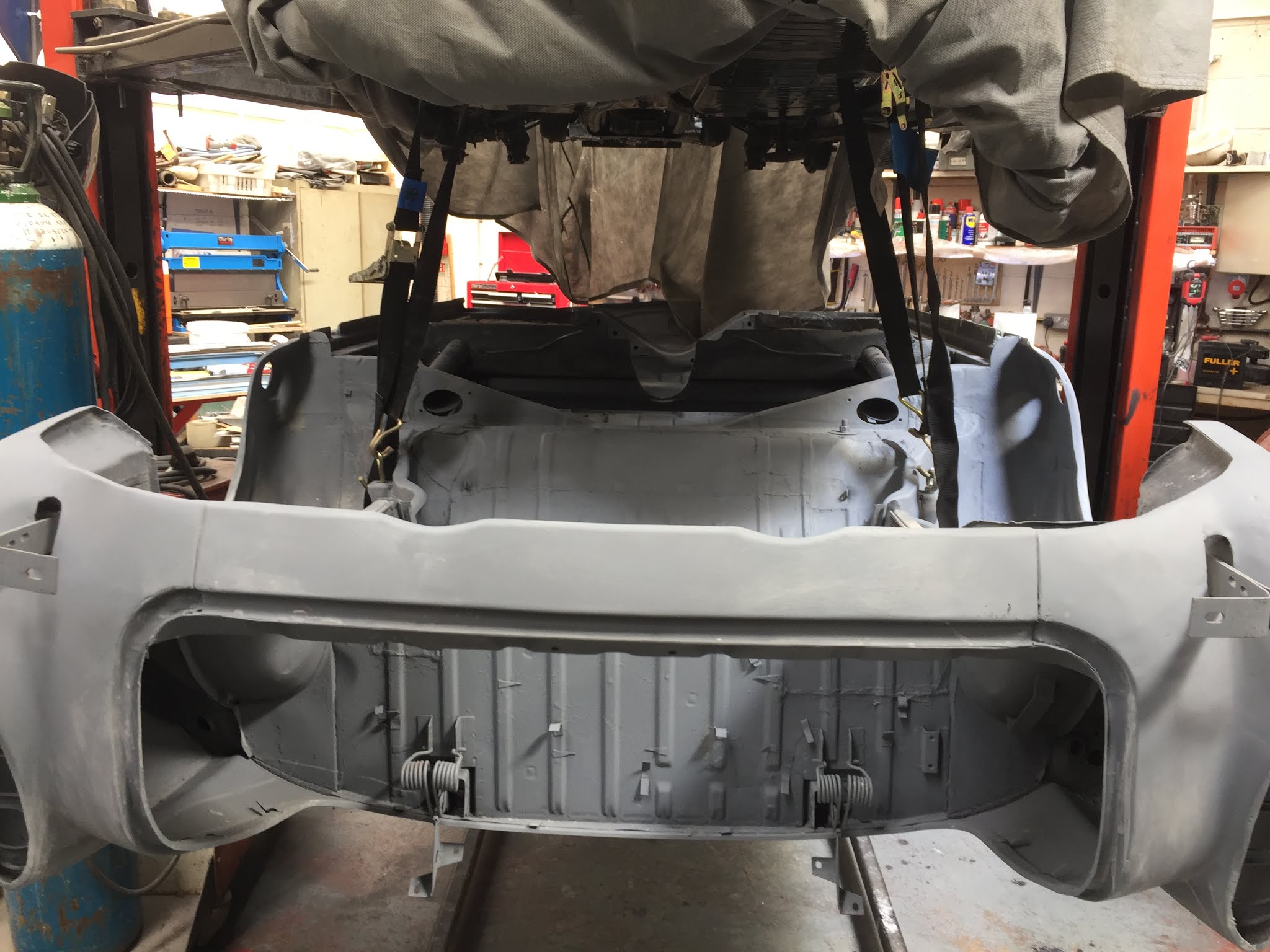
So, starting at the back of the car, the first problem to overcome was that the bumper mountings were currently being used to support the body on the rotating dolly. The answer was to hang the back of the body on ratchet straps from the hoist. The dolly could then be removed leaving the bumper mounting brackets clear.  So, full of anticipation, I took the new rear bumper and offered it up to the body, only to find that it would not fit around the car body. The bumper was, in fact, about 3cm too narrow. The ends of the bumper, that wrap around the body, just hit the body and would not pass along the sides of the car. 


Now these bumpers have no adjustment, so this left me scratching my head for a while before I decided to make them adjustable by cutting slots in the fixings behind the overriders, where they can't be seen. This involved converting the square holes into slots using a Dremel and small cutting discs. During the process of cutting these slots in both bumpers I got through 24 miniature cutting discs. 


Once cut, I could then extend the bumpers until they fit around the car body. As you can see, each side needed extending about 1cm. 

Once the bumper was extended I could then look at the problem of fixing the front ends of the bumper to the body. Now originally this was achieved by a bolt passing through the body, under the rear wing, then through a spacer and into a captive nut on the bumper. Now this presented another problem as the hole on one side had been plated and on the other side the wing had been replaced and there was no hole in the new part. So how to get the holes in the right places and how to get them level with no way of simply measuring the position.

After studying the problem I noticed that on the side that had been plated, I could still make out where the hole used to be. So I used a laser on a tripod to level the car on the hanging straps and then set the laser on the position of the original mounting hole. After that I moved the tripod to the other side and pointed the laser at the new wing and that gave me the correct position for the hole on that side. Now I could drill the two holes and mount the bumper on its brackets. Now, leaving the adjustable slot bolts loose, I could move the bumper ends until they lined up with the holes and, after making some new aluminium spacers, bolt the ends of the bumper to the body.

The story doesn't end here, because the rear bumper has two more mountings that fix behind the overriders directly to captive nuts on the body. Or at least they would if the fixings were there. But I had replaced the rear valance. The new valance had no fixings or holes and the support brackets had been cut off the old engine trays. Fortunately I had saved them. So I had to carefully cut the old brackets off the pieces of old engine tray then cleaned and rustproofed them and then welded new captive nuts into them. The next job was to get them in the right places. 

This was achieved by marking the holes through the bumper brackets onto the rear valance and then removing the bumper from the body again. I could then drill the holes in the valence and then offer the renovated brackets and bolt them in place through the new holes. I could then weld the brackets in place and paint them and the Bumper could then go back on and it finally fits.

Now all I had to do was do it all over again for the front bumper, which of course did not fit either. But after cutting slots, drilling holes and making more spacers, the front bumper fits too. I think four days to fit two bumpers must be a record?

So one more job on this episode was to make and fit the support platform that is under the rear seat. Now I had some material left from the panel that I bought to replace the rear bulkhead and it already had pressing ribs in it to give it strength. After measuring the panel I found that I just had enough and so confidently measured and cut the piece out that I needed. I offered it in place and found that it fit perfectly. So now I had to bend it. I took it to my press only to find that it was too long to fit in the press. So I had to cut my perfect panel in half so that I could bend the front fold over on it. 

Well I soon discovered that bending a panel with pressing ribs in it on a small manual press is not easy, but eventually I managed to bend the two halves and then weld them into place in the body and paint them. 

So there it is in place. 

My next job is to repair the two kickboards under the rear seat, which have bad rot that needs cutting out and replacing. More about that on the next episode. 


Copyright 05.06.21 all rights reserved.

My Other Blogs:
1961 BSA A10 Super Rocket Motorcycle:
http://60sclassicmotorbikes.blogspot.com/2012/07/before.html

1961 Ariel Arrow Super Sport Motorcycle :
http://60sclassicmotorbikes.blogspot.com/2014/01/1961-aerial-golden-arrow-restoration.html

Miniature Land Rover Defender:
http://miniaturelandrover.blogspot.com/2016/02/1-miniature-land-rover-defender-idea.html?view=timeslide

Motorcycle Trailers / Caravans:
http://motorcycletrailersandcaravans.blogspot.com/2018/01/1-motorcycle-trailers-problem.html


Tuesday, 30 March 2021

19. Karmann Ghia Restoration - Body Prep


Well it's time for hours and hours of body preparation and some final welding.  So starting at the front of my Karman Ghia Convertible I began the slow process of rubbing down and filling. I decided to slowly work my way around the car and started with the front valance. Because this car has had so many replacement panels, blending in the joints between old and new panels required multiple layers of filler and shaping then more filler etc.

But slowly the car began to turn from orange to grey. One of the biggest problems was to get the two rear wings the same shape. As I mentioned before, this car had had accident damage on the  left side so when I stood at the back of the car and looked at the two rear wings, it was obvious that the right wing had a good bulbus curve on it and that the left rear wing was much flatter. Now the problem was how to replicate the curve on the right wing onto the left.


To achieve this I bought a long 20" Shape Gauge and used it to capture the shape of the right wing and then transferred the gauge over to the left wing and built up the filler over multiple layers until the gauge fitted over the curve the same on both wings.


The next big problem was the bulkhead panels behind the back seat and over the gearbox. After very long consideration of the possibilities of making patches for this panel, which was really badly perforated, I finally decided to buy a new panel and cut the areas out that needed replacing.

So out came the angle grinder again and large pieces of the new panel were grafted in.


You will notice that the step in front of the replaced panel, that supports the seat, is also in a bad way. So the next step was to cut this out too and fabricate a new one.

In recent weeks I have been approaching various paint sprayers with a view to finally getting the finished coat on the body. I have been amazed at the enormous differences between quotes, but I think that I have finally decided upon the right supplier.


One final bit is that my tyres have finally arrived and I was able to get them fitted to the wheels, but fitting the wheels is a long way away at the moment.

Thursday, 3 December 2020

18. Karmann Ghia Restoration - The Body Comes Home


Well, there were a couple more welding jobs to do, which includes slowly working our way around the body. So starting at the front there were two areas that needed attention on the front valance. This involved cutting away the lower corners, welding in new shaped metal and then sanding off the welds to give a smooth new finish.


The next stage was to make a start on rebuilding the bulkhead over the gearbox area. This particular area of metal is badly perforated but we decided that it made more sense to patch this area than try and replace the whole panel as it is under the car and over the gearbox and will never be seen. This will add more strength to the perforated areas, rather than cut them out and replace them. 


As you can see, the final result was very successful and there are several other small areas of this panel that will need similar attention once the body is back home in my workshop. 
As we moved around to the back of the car, one area that needed attention was the bottom corner of the rear boot seal area. As you can see from the photo, the metalwork in this area had completely rotted away and had previously been rebuilt with body filler. This involved making several templates for five different pieces to fabricate the missing bits.


After some very careful welding the rebuilt corner was finally in place. Now true to form, just as I think that we are making progress a major problem is discovered. 

After fitting the rubber seal and closing the engine cover lid, it was discovered that there was a 2cm difference between the body and the engine cover lid on opposite corners. After investigation it was revealed  that the whole left hand corner of the body had been pushed forward during a previous accident and instead of pulling it out during that repair, they had simply made up the difference with vast thicknesses of body filler. Now with the filler removed the true extent of the damage was revealed. 

The very hard decision was made to turn the body back upside down, cut all of the welds to all of the panels in the rear quarter, including the engine compartment and then use a hydraulic ram to push the offending rear panel out to the correct position so that the engine compartment lid fit properly. This was done and then all of the connecting panels were rewelded. This whole process took 6 hours to do, but at least it is now right.


Well only two more bits to do and then the body can be transported back to my workshop, and that is fitting the headlight bowls. This involved some very delicate TIG welding so that the welds did not interfere with the headlight rims.


So after two and a half years, at last, the body was transferred onto the transporter and it was on it's way home! 


With the body finally back home, I can now concentrate on preparing the body for paint. This will require a good deal of preparation on the underside before progressing to the upper bodywork. I'm under no illusion, the first and worst job will be to remove 50 year old underseal from the original panels that have not needed replacing and I am sure that this will reveal more holes and more welding needed. 


The process for preparing under the car is as follows: 
Remove old underseal with a heat gun and scraper. 
Rotary wire brush to remove remaining debris and rust.
Treat with rust killer (Black)
Seam Seal all joints
Spray with deep etch undercoat paint (grey)
Spray with Stone Chip paint. (White)

When the car finally goes to the paint shop it will receive a full undercoat over all surfaces and then a final top coat colour.

Well that's it for now, much more to come.

You can contact me on hopcroftscoot@gmail.com

Copyright 03.12.20 all rights reserved.

My Other Blogs:
1961 BSA A10 Super Rocket Motorcycle:
http://60sclassicmotorbikes.blogspot.com/2012/07/before.html

1961 Ariel Arrow Super Sport Motorcycle :
http://60sclassicmotorbikes.blogspot.com/2014/01/1961-aerial-golden-arrow-restoration.html

Miniature Land Rover Defender:
http://miniaturelandrover.blogspot.com/2016/02/1-miniature-land-rover-defender-idea.html?view=timeslide

Motorcycle Trailers / Caravans:
http://motorcycletrailersandcaravans.blogspot.com/2018/01/1-motorcycle-trailers-problem.html

Saturday, 4 July 2020

17. Karmann Ghia Restoration - Fitting the Engine & Gearbox


Well, following my last blog, my next job was to replace the rear torsion bar end cap rubbers, that I had managed to damage. Having learnt about the mistakes I made earlier, this did not pose too much of a problem. The trick was to take the tension off the torsion bar. Then fit the rubber followed by the end cap, with the bolts just loose enough to still allow the spring plate to be re-tensioned. And then, once the bar was tensioned and the spring plate was back on its rest, finally tighten the four end cap bolts. This worked a treat and now I'm happy with the rear suspension.

So now it's time for the main event, and that is fitting the Gearbox and Engine. Well, fitting the gearbox is easy. It simply slides into place onto the front mounting rubber and mounts at the rear with the cross-member fitted with two more mounting rubbers. Care has to be taken to ensure that the gear change rod fits comfortably into the universal joint just inside the chassis. 

The two big bolts fixing the cross-member to the chassis need to be really tight as they not only hold the gearbox in place but also take the weight of the engine. So I was careful to look up the correct torque and tighten them to the right setting.


It was now a case of fastening the gear change rod into the universal joint.There is a small indentation in the rod from the gearbox and the grub screw on the coupling needs to locate into this indentation perfectly. This wasn't quite as easy as I'd hoped and in the end, I had to disassemble the coupling, whilst still in place,  and slide it into place on the gearbox shaft and then rebuild the coupling all down the small hole in the chassis. But that done it worked and the grub screw could be tightened up and locking wire fitted.

I could now test the gear change for the first time since the gearbox has been overhauled and, to my concern, I could not select 1st gear, no matter how I tried. 2nd, 3rd, 4th and Reverse were all fine. I decided not to panic  and wait until the engine was running and turning the gears inside the box and then try again.

Three more jobs now and the gearbox installation is done. 

First I had to fill the gearbox with oil. So I bought the correct gearbox oil and filled the gearbox until it just came out of the filler hole. 

Second I needed to fit the earth strap between the gearbox and the chassis around the front rubber mounting. Now I know I stripped the proper braided earth strap off the car when I removed the gearbox in the first place. But now I can't find it. So I ordered a new one from VW Heritage and they are out of stock. Now I remember the problems you can get if this earth strap is not in place as all the electrical power, when you operate the starter motor, has to find its way back to the chassis somehow and it finds that route down the clutch and accelerator cables and I've actually seen them glow red hot, which ruins the cables. So although I've ordered a new earth strap, I decided to make a temporary heavy duty one, just in case I forget a few months down the line.


The final job on the gearbox was to fit the new clutch thrust bearing. This bearing has two spring clips holding it in place and no matter how I tried, I couldn't work out how they fit. Fortunately, there is always the internet and after a little studying I soon figured it out and on it went.


The next job was to install the new drive shafts. I had already checked the condition of the constant velocity joints on the old ones and decided to replace them. It came as a surprise that two new complete drive shafts were actually cheaper than four constant velocity joint service kits. So two new shafts it was. After filling the constant velocity joints with graphite grease, the shafts could be fitted. These are held in place with six "Torque" screws on each joint and it is not easy tightening these up to the correct torque settings without damaging the small internal star socket on the end as the size is quite small and the torque quite high. 


One final job now and I can move onto the engine, and that is the starter motor. Now I know that the starter motor works OK as I had started the engine before I stripped it for renovation and it always seemed to be fine. So it was just a case of cleaning and painting it.

Well, as you can see, it was very dirty and greasy. But with a good clean and a coat of chassis black it came up a treat and a quick test on the bench proved that it was still working fine. 


So now, at last, It's time to fit the engine. 
Now I rebuilt this engine back in January 2018, but up until now I have had no way of testing it. Now I was going to get my chance. The Engine slid into its mountings easily and the four bolts soon had it firmly in place. Next I had to rig up a temporary fuel tank. This was achieved by placing a 1 gallon petrol can  at the front of the chassis and running a flexible hose into it from the fuel pipe on the front of the chassis. I then needed a 12v cable, from the battery feed to the starter motor to the HT coil. And finally I needed to devise a way to stand at the back of the engine and work the starter.

I did this by mounting a large red push button switch into a plastic box with a length of cable with two spade connectors on the end of it. These connectors went on the main battery feed to the starter and the other one to the solenoid connector. Now when I press the push button with my foot, the solenoid is activated and the starter turns the engine. 

Well it was time for the first attempt and this didn't go so well. I had petrol leaks and no sign of life from the engine. However, after a backfire, I realised that the timing must be out and started to investigate. I soon discovered that I had the HT leads 90 degrees out, so the spark was going to the wrong cylinders. A quick alteration on the distributor and, after curing the fuel leaks, the engine started and it sounded great!!!

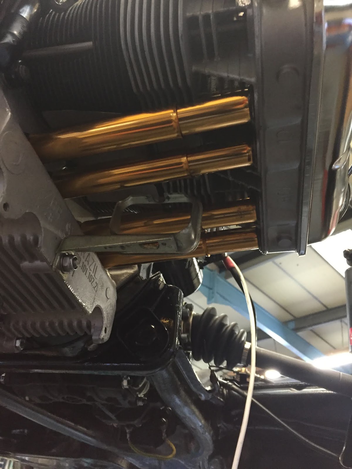
Now the bad news. It had an oil leak!  Investigation indicated that the push rod tubes were leaking on the left side.  Now despite me having replaced all of the push rod tubes and seals with new ones, I decided to do it again. So I ordered all new tubes and seals again and some special aircraft grade sealant and stripped the engine again.

The new tubes and seals arrived and I rebuilt the engine with great care. I started it again and it still leaked. I said a few choice words and stripped it again. 

This time I decided to spend more cash and buy the special push rod tubes that are spring loaded. I must admit they are far superior. It was during the rebuild again that I finally spotted the true problem. I noticed a small drop of oil on the bottom of the oil cooler and realised that it was not the push rod tubes that were leaking at all. The oil was running off the bottom of the oil cooler inside the fan housing and dripping down the side of the engine block over the push rod tubes. 


So having bought 24 push rod tubes and 48 seals in total I now knew the true cause of the problem and ordered a new oil cooler and seals.


So at last the engine was rebuilt and this time no leaks and to prove it below is a short Youtube film showing the engine running and more good news: With the engine running, I could now select 1st gear easily.  


Well that's it for this episode, I'm hoping that the next one will be the preparation of the body for painting.

You can contact me on hopcroftscoot@gmail.com

Copyright 04.07.20 all rights reserved.

My Other Blogs:
1961 BSA A10 Super Rocket Motorcycle:
http://60sclassicmotorbikes.blogspot.com/2012/07/before.html

1961 Ariel Arrow Super Sport Motorcycle :
http://60sclassicmotorbikes.blogspot.com/2014/01/1961-aerial-golden-arrow-restoration.html

Miniature Land Rover Defender:
http://miniaturelandrover.blogspot.com/2016/02/1-miniature-land-rover-defender-idea.html?view=timeslide

Motorcycle Trailers / Caravans:
http://motorcycletrailersandcaravans.blogspot.com/2018/01/1-motorcycle-trailers-problem.html

Saturday, 21 March 2020

16. Karmann Ghia Restoration - Big Trouble with the front Axle


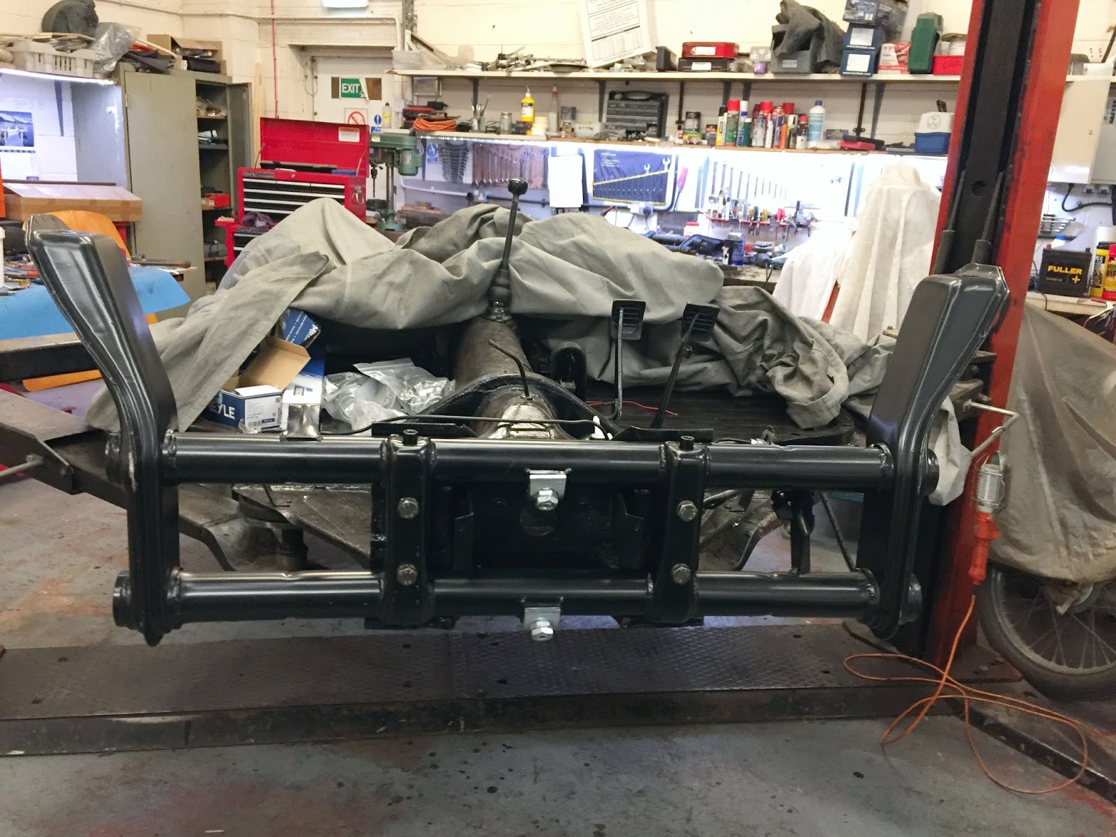
Time to look at the front axle and like most projects I started with great enthusiasm. So I stripped the front axle of all the brakes and suspension parts and removed the axle beam from the chassis. 


My next job was to remove 50 years of road dirt from the axle beam which took a very long time and then finally give the beam a coat of rust converter and then chassis black.


It was not until I had done all of this work, and laid the axle down on the bench that I noticed that the axle appeared to be BENT!
Careful measurement confirmed that  the ends were indeed bent back from the centre by about 5mm. Disaster! I immediately went on the internet to see if it was a big problem. The answer was that the axle must be straight. The good news was that the internet said that, with a good press, it was possible to straighten it.

So I took the axle to my friends workshop and we carefully supported the ends  of the axle on wood and then applied pressure to the centre struts of the axle, via another piece of wood in his press.

After a fair bit of pressure, the axle tubes straightened and we checked the tubes with a straight edge to ensure they were now level.


We were feeling pretty pleased with ourselves that we had achieved until I got the axle back to my workshop and I happened to turn the axle over and spotted what had happened to the axle end caps.

They had both crushed, under the weight of the press and were now beyond use. All of that work was now wasted and I had to find a replacement front axle.

That was not as easy as I thought, as no standard replacement axles were available, even in the USA.

So, in the end, I had to settle for an adjustable front axle. It's basically the same but the centre clamp points for the torsion bars are adjustable, allowing you to lower the suspension, if desired. Now as I don't want to lower my suspension these adjusters will just have to be set at the top (standard position). But there it is, fitted to the chassis and now I've got to rebuild it.


Stripping the old axle revealed another problem. Two of the leafs in the torsion bars were broken in the top tube. I doubt if I would have ever found that had the axle not been replaced. So now I had to order new torsion bars.


Along with the new the new torsion bars, I ordered all new ball joints and track rod ends. Now here comes the next mistake. The trailing arms cleaned up beautifully and I took them, along with the new ball joints back to my friend's workshop to have the old ball joint pressed out and the new ones pressed in. It took 8 tons of pressure to do this.


I took them back to my workshop and fitted them  onto the new axle along with the renovated stub axles and new shock absorbers.

I wasn't over concerned, as everything was new, but the ball joints did seem very tight and so, just to be sure, I went back on the internet only to discover another problem.

The ball joints have notches in their caps and, according to the web, these notches have to be orientated front to back on the car. I had noticed the notches but had not checked what they were for. Now I had to go back to the car and check where the notches had finish up after we had pressed them in.

As luck would have it, three of the four ball joints were in the right orientation (Pure luck) but the upper right was 90 degrees out. So I had to order another ball joint and strip that side again, take it back to my friend, and replace the ball joint again.  I didn't want to chance refitting the first one again in case two lots of pressing had damaged it.

It was about time I had a bit of luck and that came with the steering box. I fully expected to have to overhaul it. However  inspection revealed absolutely no wear and no play. So it was just a case of cleaning it up and fitting it to the axle. The new axle has no mounting lugs, so I've had to estimate it's position and I'll have to adjust that once the body and steering column are back in place.


Time to clean up and refit the anti-roll bar with all new rubbers and clamps. No great problems there in fact I think it fits better that it did originally.

What was difficult was refitting the grease nipples, which would not cut into the holes in the new axle and in the end, I finished up fitting new ones. I also treated myself to a new , air powered, grease gun and I've been pumping grease into this new axle for some time now and still haven't managed to fill the new empty tubes yet. I now need to buy more grease.


It's now time to renovate the track rods and replace the track rod ends. No great problems here.


And complete with a new steering damper they were soon fitted.


Now, at last I could fit the brake back plates and the new discs, complete with all new wheel bearings and oil seals.

One problem, after fitting the discs was that the grease caps, that came with the discs didn't fit over the bearing clamp nut and the old caps are not fit to use. So I've had to put a new pair on back order.


Now it had been my intention to paint the new brake caliper "Red". However, when I opened the boxes, I found, to my surprise, that the new calipers were chrome plated. Now I don't know how good the chrome is but I felt it was worth leaving them as they are and see how they weather. I have already bought the red caliper paint, so if they do begin to rust I can always paint them later.


My next job is to replace the rear suspension, torsion bar and cap rubbers, that I have ruined, and then I'm going to reinstall the gearbox, that has already been overhauled.


You can contact me on hopcroftscoot@gmail.com

Copyright 21.03.20 all rights reserved.

My Other Blogs:
1961 BSA A10 Super Rocket Motorcycle:
http://60sclassicmotorbikes.blogspot.co.uk/2012/07/before.html

1961 Ariel Arrow Super Sport Motorcycle :
http://60sclassicmotorbikes.blogspot.co.uk/2014/01/1961-aerial-golden-arrow-restoration.html

Miniature Land Rover Defender:
http://miniaturelandrover.blogspot.co.uk/2016/02/1-miniature-land-rover-defender-idea.html?view=timeslide

Motorcycle Trailers / Caravans:
http://motorcycletrailersandcaravans.blogspot.co.uk/2018/01/1-motorcycle-trailers-problem.html